
Brackets and mounts
Design a mounting bracket around its hole pattern
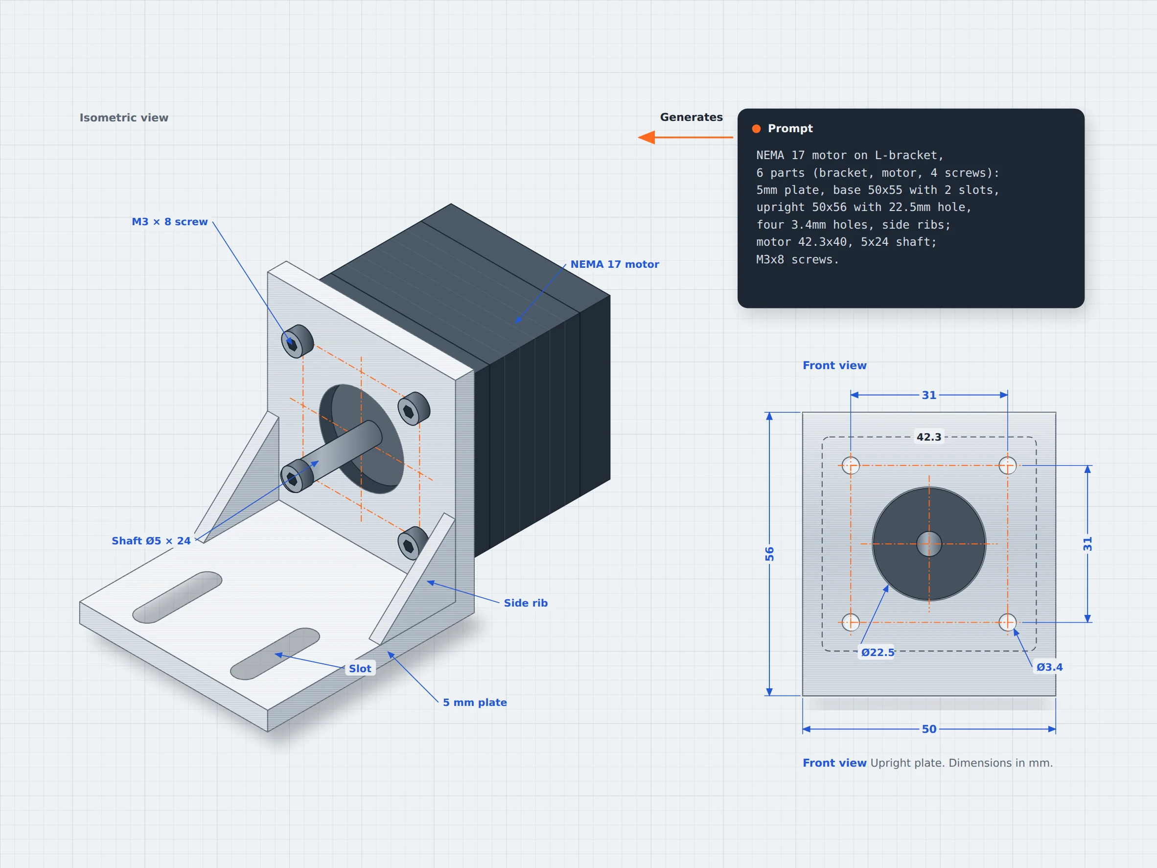
Efficient mounting bracket and motor-mount design powered by AI CAD. Leverage proprietary content—existing hole patterns, slots, ribs, and motor-mount cases—to accelerate iterations from concept to production with zCAD. AI.
01 / The engineering challenge
Why every bracket starts from a blank sketch
A mounting bracket needs to do more than connect two components. Its mounting holes, plate dimensions, clearances, and support features must match the parts it is designed to hold. These details need to be defined before the design can be reviewed because the features need to be positioned correctly for the bracket to fit its intended application.
Mesh model limits
Every hole starts as a sketch
Hole pattern, slots, and ribs are each drawn, dimensioned, and constrained before the bracket exists.
The hardware has to be modeled too
To check fit, the motor and screws need to be in the assembly, mated by hand.
Each variant is another round
A different motor or a thicker plate means going back into sketches and mates.
02 / Connected capabilities
A bracket built around the hardware you have
Describe the components the bracket needs to hold, along with the dimensions and hole pattern they require. zCAD. AI generates a CAD model, which you can inspect and refine in zCAD. Online.

Generate a bracket from a description
Describe the bracket's overall shape, plate dimensions, hole pattern, slots and support features to create an initial model.
Define component geometry
Specify plate dimensions, hole positions, spacing, and other required features, then inspect the generated geometry against your requirements.
Refine individual components
Request changes to the bracket’s dimensions or features in zCAD. AI, or edit available CAD features and dimensions in zCAD. Online.
Review the assembly
Inspect the relative positions of the bracket, mounted components, and fasteners. Check their arrangement and clearances against the intended design.
03 / From requirement to delivery
From a bracket brief to a CAD model
Define what the bracket needs to hold, the dimensions of its mounting interfaces, and the features required for the design. Generate an initial model with zCAD. AI, then review and refine the geometry in zCAD. Online.
Describe the bracket
Specify what the bracket needs to mount, its overall dimensions, plate thickness, hole patterns and slots.
Generate an initial model
Enter the description in zCAD. AI to generate an initial CAD model.
Review the model
Review and refine the geometry, if the result differs from the intended design, revise the prompt and check the updated model against your requirements.
Continue in zCAD. Online
Open the model in zCAD. Online to continue working with its available CAD features and dimensions.
04 / PROJECT AT A GLANCE
Project Inputs
- The parts to be connected and their intended arrangement.
- Overall size, thickness, and available space around connected components.
- Mounting interfaces, support features, and other details relevant to the application.
Expected Outputs
- An initial CAD model of the bracket
- Geometry to review against the required hole pattern
- Model that can be refined in zCAD. Online.
Typical Uses
- 3D printers and CNC: Design a motor mount around a known frame pattern.
- Robotics: Create a bracket to hold a sensor near an existing mounting face, using its dimensions and attachment points to guide the design.
- Electronics: Model a small bracket for securing a PCB or module, accounting for its mounting holes, dimensions, and nearby components.
Before you get started
Frequently Asked Questions
Can I create a mounting bracket from a text description?
You can describe the bracket's purpose, shape, dimensions, mounting holes and slots in zCAD. AI. Review the generated model and refine it to match your requirements.
Can I specify exact mounting hole patterns and dimensions?
You can include hole diameters, spacing and positions in your prompt. Check the generated geometry against the original measurements or component specifications.
Can zCAD. AI generate a bracket with ribs and slots?
You can include ribs, slots, chamfers, and fillets in your description. Check the generated model to confirm that these features are present and correctly positioned.
Can I create a bearing mount with multiple components?
You can describe an assembly with base, cap, bearing, shaft etc. Check the generated components, their alignment, and their fit against the intended design.
Can I edit a bracket after generating it?
You can request changes through prompts in zCAD. AI or open the model in zCAD. Online to continue working with its available CAD features. After making changes, verify that the dimensions and related features still meet your requirements.
Will a generated bracket be strong enough for my application?
Not automatically. You need to assess the material, dimensions, and expected loads for the intended use.
zCAD / Brackets and Mounts
Start your bracket from the hole pattern
From motor mounts to bearing supports, describe the components you need to connect, generate a CAD model, and refine its geometry against your requirements.