
3D-printed parts
Create functional CAD parts for 3D printing
Tell zCAD. AI what you need to print and what it attaches to, and it generates a 3D model where every size you write becomes a dimension you can check and change. Review the generated model, refine its dimensions if needed, and export it.
01 / The engineering challenge
Why a mesh model may not work as a printed part
A 3D-printed part often needs to do more than look right. It needs to fit an existing profile, align with mounting holes, accommodate fasteners, or connect securely to another component. Mesh models can make it harder to adjust dimensions and connection features precisely.
Mesh model limits
Dimensions may not match
A mesh only approximates the shape and size of a part. A hole intended to be 6 mm wide might end up slightly smaller, so an M6 bolt might not fit.
One change can mean starting over
A mesh has no editable design dimensions. Changing a hole diameter or plate thickness may require modifying the mesh directly or regenerating the model.
Hard to align parts
Matching holes and surfaces between two mesh parts can take extra work.
02 / Connected capabilities
Printable parts that keep their real dimensions
Describe the part's purpose, dimensions, and mounting features. zCAD. AI can generate an initial model from the description, which you can inspect against your requirements and refine in zCAD. Online.

Generate a part from a description
Describe the part's purpose, overall dimensions, and important features to generate an initial CAD model with zCAD. AI.
Define mounting features
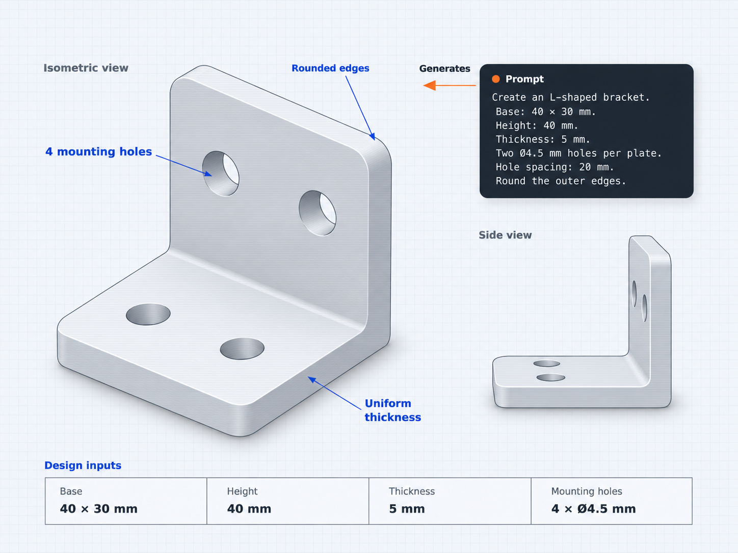
Specify hole diameter, spacing, plate thickness, and other dimensions that determine how the part connects to existing components.
Inspect the generated geometry
Review the bracket's shape, dimensions, hole positions, and other visible features against your original requirements.
Refine the design
Ask for changes in zCAD. AI, or edit features and dimensions in zCAD. Online.
03 / From requirement to delivery
From a description to a 3D-printing model
Start with a clear description of the part, generate an initial model, and check the result against your requirements. Refine the geometry where necessary before evaluating the design for its intended use.
Describe the part
In zCAD. AI, describe the part; write what a part does, its overall dimensions, and which features or connections are important.
Generate the initial model
zCAD. AI will generate it from the description, For complex designs, build and verify the main geometry before adding more details.
Review and refine
You can review it, compare the model with the original requirements. You can also open the model in zCAD. Online to continue working with its available modeling features, and make any required adjustments.
Export
From the model output options, export STL, 3MF, or OBJ files and open them in your slicer.
04 / PROJECT AT A GLANCE
Project Inputs
- Part dimensions and overall shape
- Mounting holes and connection requirements
- Important features and intended use
Expected Outputs
- An initial editable CAD model based on the prompt
- Geometry and dimensions according to the requirements
- A model that can be refined using supported CAD tools.
Typical Uses
- Model collecting: Design a stand for a 1/144 scale kit, with dimensions according to the model and available display space.
- Photography: Create a compact camera mount with defined mounting points and dimensions.
- Home and workshop: Design a hook or tool organizer with defined mounting points and dimensions as needed.
Before you get started
Frequently Asked Questions
Can I make a 3D-printable part from a description?
zCAD. AI can generate CAD models from a text description. Include the part's purpose, important dimensions, and connections to give zCAD. AI the design context it needs.
Can I model a replacement for a broken part?
You can describe the replacement part and its required interfaces. Measure the original component carefully and verify the generated geometry against those measurements before manufacturing.
Can I edit the model after it’s generated?
You can open the AI-generated model in zCAD. Online and continue working with the modeling features available for the model.
What should I put in my description?
Describe part's function, overall dimensions, mounting points, connection requirements, and any features that must remain fixed. If a critical measurement is unknown, obtain it before relying on the model for manufacturing.
zCAD / 3D-Printed Parts
Make your next printed part in CAD
From custom mounts and brackets to replacement components, begin with a clear description and develop the design through review and iteration.