
Robots and mechanisms
Design a robot gripper around its mounting interface
Describe a mechanism and the parts it needs. zCAD. AI turns it into an editable CAD assembly, with dimensions and mates you can check and change.
01 / The engineering challenge
Why a mesh gripper can't carry its mates
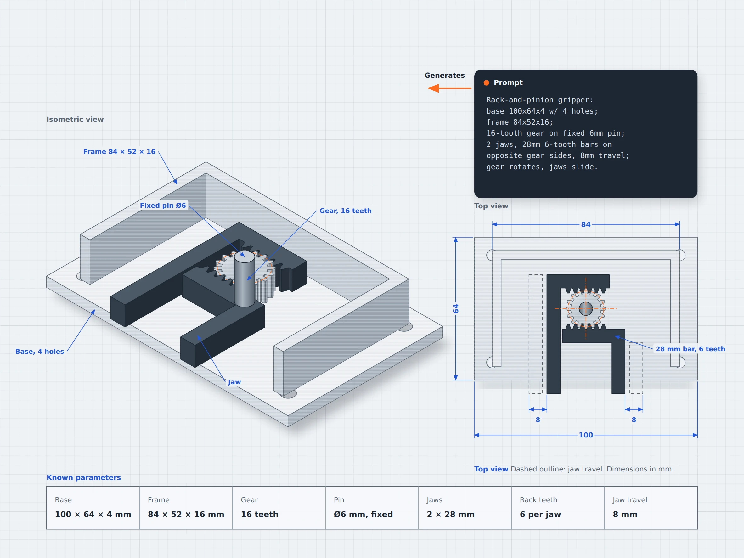
A mechanism is more than a collection of parts. The components need to fit together, and their dimensions matter when you want to change the design or build a working assembly. For example, the gear, toothed racks, jaws and mounting plate must be positioned according to the design requirements.
Mesh model limits
Separate shapes do not guarantee a usable assembly
A mesh model may show all the parts in approximately the right position but it does not inherently preserve editable dimensions or assembly relationships.
Small dimensional changes affect the fit
If a jaw gets wider or a mounting hole moves, the parts may no longer fit. With a mesh, that can mean regenerating the model.
Appearance does not prove movement
A gripper can look complete while having poorly positioned parts, or unsuitable mounting points. Its geometry and intended operation still need to be checked.
02 / Connected capabilities
Robot parts that keep their mates
Describe the parts, dimensions, and intended connections to generate an initial CAD assembly. Review the component arrangement and refine the design in zCAD. AI and zCAD. Online.

Generate a multi-part assembly
Describe the main components, their dimensions, and how they should be arranged to generate an initial CAD model.
Define component geometry
Specify gear sizes, jaw dimensions, mounting holes, and other features, then inspect the generated geometry against your requirements.
Refine individual components
Request changes such as adjusting jaw width or changing the mounting plate dimensions in zCAD. AI, or edit available CAD features and dimensions in zCAD. Online.
Review the assembly
Inspect the relative positions of the gear, racks, jaws, and mounting features. Check whether their arrangement meets the intended design before validating the mechanism's movement.
03 / From requirement to delivery
From a mechanism brief to a CAD assembly
Define the mechanism's components, dimensions, and mounting points. Generate an initial assembly with zCAD. AI, then review and refine it in zCAD. Online.
Describe the mechanism
In zCAD. AI, explain what the assembly should do, list its main components, specify their dimensions, and describe how the parts connect.
Generate the initial assembly
zCAD. AI generates the CAD model from your description. Review the generated components, dimensions, gear arrangement, and overall assembly.
Review and refine the design
If needed, refine the design; request the changes in zCAD. AI, such as adjusting the jaw spacing or changing the mounting plate dimensions. Check whether the requested changes preserve the intended arrangement.
Continue in zCAD. Online
Open the model in zCAD. Online to work with its available CAD features and dimensions.
04 / PROJECT AT A GLANCE
Project Inputs
- Overall assembly dimensions
- Component sizes and shapes
- Gear and rack arrangement
Expected Outputs
- An initial CAD assembly with multiple components.
- Separate components to inspect and refine.
- Mounting features and gear arrangement to review.
Typical Uses
- Educational robotics: Design interchangeable gripper fingers for classroom robots to explore different gripping shapes and sizes.
- Lab automation: Create holders sized for sample tubes, with mounting features suited to the equipment layout.
- Drones and RC projects: Design camera mounts or arm connectors around the required dimensions and mounting points.
Before you get started
Frequently Asked Questions
Can zCAD. AI generate a robot mechanism with multiple parts?
Yes, zCAD. AI can generate individual parts and assemblies with multiple components and their mates. Describe the required parts, dimensions, and connections, then check the generated result against your requirement.
Can I create a gripper or robot joint from a text description?
You can describe a gripper, joint, or any other mechanical assembly, including its main components and dimensions. The generated geometry may need several rounds of refinement, and you should verify that it suits the intended mechanical function.
Can I change the individual parts after generating an assembly?
Yes, you can request revisions in words in zCAD. AI, such as changing dimension of a jaw, while keeping the mounting hole pattern unchanged. You can also open the model in zCAD. Online to work directly with its available CAD features and dimensions.
Can zCAD verify that my mechanism will move correctly?
A generated CAD assembly does not prove that its motion will work correctly under real operating conditions. You need to validate the intended movement and mechanical performance separately.
Can I 3D print the parts of a robot mechanism?
You can export STL, 3MF, or OBJ files and open them in your chosen slicer. Before printing, check each part's dimensions, material requirements, and suitability for the expected loads.
zCAD / Robots and Mechanisms
Build the gripper as an assembly
From robot grippers to joints and gearboxes, start with a description of parts you need and how they connect. Generate an assembly, review its dimensions, and refine the design before building it.